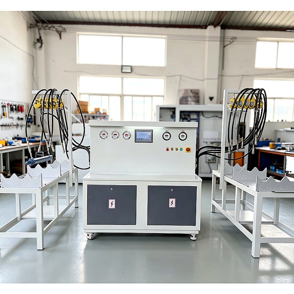
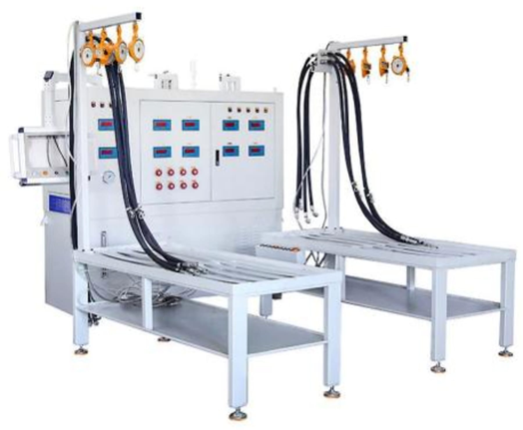
This test bench is mainly used for factory delivery tests of hydraulic cylinders, and can meet all factory test items specified in GB/T 15622-2005 Test Methods for Hydraulic Cylinders:
Pulse test (adjustable pulse times and pressure; function can be shut down when not in use)
Combined flow test pressure of the test system: 10 MPa; maximum theoretical output flow: 225 L/min (pump displacement: 150 mL/r), driven by a 4-pole 55 kW motor
High-pressure test pressure of the test system: 45 MPa; maximum theoretical output flow: 9.0 L/min, driven by a 4-pole 11 kW motor
Circulating filtration & cooling system: max working pressure 2 MPa; maximum theoretical output flow 160 L/min, filter precision 10 um, oil chiller power 9.6 kW (10 HP)
Specification of test cylinders: outer diameter <= 250 mm; full extension length <= 10 m
Equipped with 2 groups of main oil circuits: test 5 cylinders in one batch, then another 5 cylinders; independent test data for each single cylinder
Floor area of the test bench: 5 m (width) × 15 m (length). It mainly consists of power station & control console, test bench frames and interconnected pipelines. See the layout drawing below:
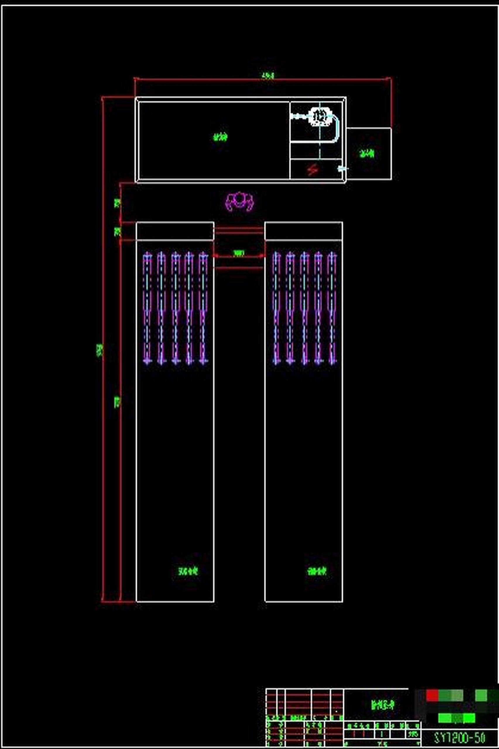
Main components: oil tank, oil tank support, motor-pump units, valve blocks, pipelines, hose suspension brackets, etc.
Oil tank: Welded steel plate structure; internal & external surfaces pickled, phosphated and plastic-sprayed
Oil tank support: Welded rectangular tube & steel plate structure; oil collecting platform at the bottom for waste oil recovery. The oil tank is mounted on the upper part of the support; motor-pump units, valve blocks and pipelines are installed around the inner side of the support with surrounding access doors for neat layout and safety protection
Motor-pump unit: Horizontally mounted on the motor flange via pump base, installed on the lower platform of the support
Control valve assembly: Plate-connected valves mounted on integrated valve blocks to realize various control functions
Pipeline system: Composed of hard pipes, hoses, flanges, connectors and seals; hard pipes pickled & phosphated with outer surface painted
Hose suspension bracket: Assembled with square tube frame, lifting rings and balancers; bracket length approx. 0.9 m, equipped with 10 hooks and 10 balancers respectively
Two sets of test bench frames in total, each frame can hold 5 test cylinders. The test bench frame is used for cylinder fixing and residual oil draining after testing. Tabletop height: 750 mm, width: 900 mm, total length approx. 10 m. It supports simultaneous testing of 5 cylinders with outer diameter φ50-φ250 mm and full extension length <= 10 m.
The frame body is welded with high-strength rectangular tubes and steel plates. Linear guide rails are machined and laid on the tabletop; two cylinder barrel supporting seats are installed on the guide rails. The left end of the test cylinder barrel is clamped by ratchet binding belts. Compressed air is used for oil drainage after test completion. Test hoses are suspended by balancers on pipeline brackets. An oil collecting tray is arranged at the bottom to collect leaked and residual oil, which can be drained via a manual ball valve.
5 V-shaped grooves are arranged on the V-type cylinder barrel supports of each frame for simultaneous placement of 5 cylinders. Test hoses and quick connectors are mounted at the end of each frame. An oil collecting tank is arranged under pipelines with leak plates for collecting dripping hydraulic oil and storing test hoses. An oil collecting pump set and filter are installed inside the collecting tank to automatically filter recovered oil and return it to the oil return zone of the main tank. The collecting tanks of the two frames are connected by pipelines, sharing one set of oil collecting pump for oil recovery and filtration.
This hydraulic cylinder test bench is composed of hydraulic test system, electrical control system and measurement & display system.
The hydraulic test system includes high-pressure loading system, low-pressure combined flow system, pilot control system, auxiliary system and oil temperature control system.
The high-pressure system adopts an RK radial piston pump with flow 9.04 L/min driven by a 4-pole 11 kW motor. Two groups of 50 MPa rated electromagnetic ball valves and check valves are used to conduct pressure resistance test on two chambers of test cylinders separately. The pump automatically unloads once the set rated pressure is reached. Each test chamber is equipped with a hydraulic check valve for pressure holding. To shorten pressure rising time, the high-pressure pump starts pressurization after the low-pressure pump reaches a preset pressure (the trigger pressure can be set on the touch screen). Pressure can be adjusted via manual remote control.
The low-pressure combined flow system uses a vane pump with displacement 150 mL/r driven by a 4-pole 55 kW motor for low-pressure reciprocating test of cylinders. The vane pump can output three flow rates: 65 L/min, 135 L/min and 200 L/min, selectable via human-machine interface (adjusted by motor speed control) to meet test requirements of different bore size cylinders. During pressure resistance test, the low-pressure combined pump automatically unloads after the cylinder travels to both stroke ends, and the high-pressure system continues pressurization up to 45 MPa.
① Filtration system: Ensures cleanliness of hydraulic oil. A 100 um suction filter is installed at the oil suction port of main test pumps; a 10 um return filter is arranged on the oil return pipeline after cylinder testing, so all oil returning to the main tank is filtered before entering the oil return zone, coordinated with the temperature control system. ② Temperature control system: Equipped with a 10 HP industrial chiller for bypass circulating cooling with automatic operation mode. ③ Liquid level controller on the oil tank with low liquid level alarm function. ④ Oil particle contamination detection: Equipped with oil particle counter and peristaltic pump for continuous detection (2-3 times), with test results displayed on the counter.
Composed of electrical cabinet and button box. Centralized control mode is adopted: main circuit AC 380 V, control circuit AC 220 V & DC 24 V. All test actions and safety protection logics are processed by PLC.
Consists of PLC data acquisition modules, sensors, touch screen, indicator gauges and operation panel. Operators can set test parameters and view/store test data. The system collects and processes parameters including system pressure, minimum starting pressure, oil temperature, holding pressure, holding time, pressure drop, reciprocating cycles, etc., and automatically generates and stores test records. All control gauges and remote pressure regulating valves are mounted on the panel, with sound-light alarm for filter clogging and running status indicators for intuitive operation monitoring. The operation panel is installed on a cantilever bracket with left-right swing and angle adjustment function.
Combined pressure oil source: high-pressure small-flow pump + low-pressure large-flow pump. The two pumps converge for no-load reciprocating test; only the small-flow pump loads during pressure resistance test while the large-flow pump unloads automatically to save energy and reduce consumption.
Supports automatic measurement of minimum starting pressure, automatic reversing, automatic cycle counting, pump-on delay pressure holding, pump-off delay pressure holding, and collection of test pressure, holding time and other data.
Multi-stage oil cleaning: suction filtration, return filtration and bypass circulating filtration to improve cleanliness of test cylinders.
PLC control with 10.4-inch color touch screen; touch screen parameter setting combined with manual control for easy operation, maintenance and repair; general-purpose hydraulic components selected.
Operators can set reversing cycles and pressure holding time on the touch screen to realize fully automatic testing and improve production efficiency.
| No. | Name |
| 1 | 55 kW + 11 kW Motors |
| 2 | Vane Pump (Displacement: 150 mL/r) |
| 3 | RK14-8.5 Radial Piston Pump |
| 4 | CB Series Gear Pump |
| 5 | 4WE6J Solenoid Directional Valve, DBW10B Solenoid Overflow Valve |
| 6 | Check Valve, 4WE25J Electro-hydraulic Directional Valve |
| 7 | TF-630×80 Suction Filter |
| 8 | RFA-630×10 Return Filter |
| 9 | ZU-630×10,X5 Circulating Filter |
| 10 | Pressure Sensor |
| 11 | Low & High Pressure Ball Valves |
| 12 | High-pressure Hoses, Pipelines, Quick Connectors |
| 13 | PLC Programmable Logic Controller |
| 14 | Low-voltage Electrical Components |
| 15 | 10.4-inch Color Touch Screen |
| 16 | Hydraulic Check Valve, Electromagnetic Ball Valve, Overflow Valve |
| 17 | Pneumatic Valves & Other Pneumatic Components |
| 18 | Balancer |
| 19 | Temperature Sensor |
| 20 | 10 HP Oil Chiller |
| 21 | Linear Guide Sliders |
| 22 | Oil Contamination Particle Counter |
| 23 | High-pressure Manual Ball Valve |
| 24 | 55 kW + 11 kW Frequency Converters |
| 25 | Cantilever Operation Box Assembly |
| 26 | Cylinder Mounting Platform |
One complete set of test system, including oil tank, oil tank support, motor-pump units, base, integrated valve blocks, control valves, filters and connecting pipelines of all components
One complete electrical control cabinet, including PLC and all required electrical components
Technical documents including equipment operation manual, electrical schematic diagram, hydraulic schematic diagram; spare parts list and specification of all sealing elements

Jinan Parkway Auto Parts Co., Ltd. is dedicated to supplying engines and components for heavy-duty trucks, construction machinery, commercial vehicles, and marine vessels, covering both OEM and aftermarket parts.